Reality CoProcessor
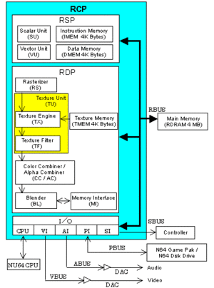
The RCP and CPU are both MIPS R4300i processors and are executed simultaneously and handle all graphical and audio functions. The difference being the RCP is a 64-bit processor with vector command extensions and runs at 62.5MHz. The RCP is comprised of the RSP, RDP (which operate independently and are connected with the XBUS) and I/O subsystem. The RCP executes tasks while the CPU executes threads which run parallel when accessing main memory. The CPU controls the RCP through DMA (to transfer the code) and SP_STATUS (to start and stop it), and communicates with the CPU through the RSP's COP0 instructions. The RCP controls essentially all peripheral access on the Nintendo 64 which includes, but is not limited to: video, audio and serial. It does this through the usage of it's proprietary 32 memory-mapped registers which are separated in memory depending on their individual function. Each of their respective divisions are 1MB in size, however the "valid" address space of accessible registers is much smaller.
The RCP also has it's own language which are called "μCodes" (256 microcodes) to direct the RSP for such things as render a frame, and are a set of C Macros. Display lists are a sequence of uCodes defined by the game. This is fed to the RSP. For more of a practical knowledge example, a good thing to note about the RCP (and vector processors in general) is it carries out operations on banks of registers as opposed to just single registers on their own. Said banks consist of a certain number of parallel registers which share the same bit width and are called a vector and uses vectors of eight registers (other vector processors can use a lot more).
Reality Display Processor (RDP)
The RDP is the graphics display pipeline that executes an RDP display list generated by the RSP and CPU. The RSP feeds the RDP (display/sound processor) commands The RDP pretty much just rasterizes rectangles and triangles with it's "Rasterizer" (DP Registers) and produces high-quality textures with it's Texture Unit. It also has a 4KB TMEM (Texture Memory) chip that is sectioned into 4 banks, a color combiner (CC) a blender (BL), as well as a memory interface. The blender is used to mix the calculated pixels and frame buffer pixels. Moreover, it's used in translucent polygon drawing, the anti-aliasing process, the fog process, the dither process, etc.
Reality Signal Processor (RSP)
The RSP is a programmable coprocessor that is also a slave processor. It essentially programs itself with the use of it's own language (uCodes). It is composed of an 8 unit parallel Vector Unit (VU), a Scalar Unit (SU), featuring a small instruction memory, IMEM (4K bytes or 1K instructions) and small data memory, DMEM (4K bytes). Software running on this processor implements a large portion of the geometry display pipeline. The two memory sections work like that of a code and data segment: IMEM = Instructions, DMEM = Data, hence the prefixes. The RSP serves the purpose of video decoding, audio synthesis and decoding and generally multiple accumulates
Synopsis:
- RSP's COP0 handles processors communication through DMA
- RSP has no COP1 for FPU
- COP2 is the RSP's Vector Unit
Data transfer rate between the CPU and RSP.
I/O subsystem
The Input/Output (I/O) subsystem exists on most operating systems for three main reasons:
- to hide device-specific details in device drivers through which the operating system transfers data and control
- to provide a fair and safe access scheme to the devices, since most of them are shared resources
- to provide a consistent, uniform, and flexible interface to all devices, allowing programs to reference devices by name and perform high-level operations without knowing the device configuration.
Usually, the I/O software is structured in layers:
- device-independent system interface
- device drivers
- interrupt handlers
The interrupt handler is mainly responsible for waking up a device driver after an I/O operation completes. The device driver performs device-specific operations, such as setting up registers for DMA and checking device status. The device-independent system interface provides a uniform interface to user-level software and common I/O functions (that is, protection, blocking, buffering) that can be performed across different devices.
For the RCP, there are two modes of I/O operations:
- DMA provides a minimum of 64-bit transfer between the RDRAM and any of the devices
- IO provides a 32-bit transfer between the CPU and any of the devices
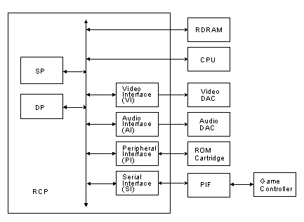
The RCP consists of the following major devices and interfaces (see Figure below):
- Reality Signal Processor (RSP)
This internal processor supports both DMA and IO operations between RDRAM and I/Dmem addresses.
- Reality Display Processor (RDP)
This internal processor supports only DMA from either RDRAM or Dmem addresses to its internal buffer.
- Video Interface (VI)
This write-only interface connects to the video DAC. It supports only DMA from RDRAM to a specific video buffer address and allows you to change video modes and configurations.
- Audio Interface (AI)
This write-only interface connects to the audio DAC. It supports only DMA from RDRAM to a specific audio buffer address and allows you to set the audio frequency.
- Peripheral Interface (PI)
This read-write interface connects to the ROM cartridge and other mass storage devices. It supports DMA as well as IO Read/Write to ROM addresses.
- Serial Interface (SI)
This read-write module interfaces to the PIF, which connects to the game controller and modem devices. It supports DMA as well as IO Read/Write to PIF RAM addresses.
Logical View of RCP Internal Major Devices and Interface Modules

The Nintendo 64 I/O software subsystem consists of the following major components:
- system exception handler
- device manager for shared devices
- device-dependent system interface
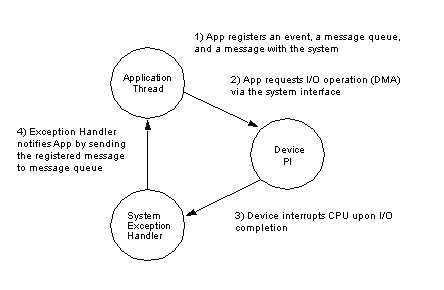
The figure below shows the interaction between some of these components to service an I/O request. This interaction assumes that the device is not shared, and therefore, requires no mutual exclusion.
CPU
fecal matter
Video Interface(VI)
The video interface reads the data out of the framebuffer in main memory and generates the composite, S-video, and RGB signals. The VI reads data from the frame buffer using a fixed time interval, and sends it to the DA (digital-to-analog) converter (video DAC) to produce the video output.
Video Interface registers
VI registers are for precise video output and control by telling you where the current screen image is being read from, color depth, and things of that nature.
VI Registers detailed and misc
Audio Interface (AI)
The AI reads data from the audio buffer using a fixed time interval, and sends it to the DA (digital-to-analog) converter (audio DAC) to produce the sound output.
Audio Registers detailed
Parallel/Peripheral Interface (PI)
Serial Interface (SI)
TEMP MISC
HLE emulators apply textures at your computer's dpi level rather that of the system video output. mmm, we love you TMEM
Anti-aliasing
Environment mapping (PSX and Saturn do NOT support this)
Load Management
Texture Mapping
Z Buffering

