N64 CPU
N64 CPU The main CPU is a MIPS VR4300i microprocessor which includes a Translation Lookaside Buffer (TLB) and Memory Management (MMU) features that are controlled with registers in the builtin Coprocessor 0 (COP0). The main CPU also has a Coprocessor 1 which was a Floating Point Unit (FPU).
The CPU's MMU had a negative performance impact when a game used a lot of virtual memory addresses. Thus, a lot of games directly use physical memory.
MIPS Architecture
Main article: MIPS The MIPS Architecture (RISC) works great with a slower memory bus, due to having more registers and fewer addressing modes. Another benefit over an x86 (CISC processor) is not having to access status/flag registers after ever instruction. While the VR4300i is in the R4000 series and supported MIPS III instructions, the N64 SDK compiler generated only MIPS I instructions as though for an R3000 level processor.
Opcodes
Main article: Opcodes
Todo: Short Description Here.
Registers
Main article: Registers The MIPS Architecture and instructions are designed to support 32 registers of whichever type are needed.
- The Main Processor has 32 General Purpose Registers (GPR) which are 64 bit (8 bytes).
- The Coprocessor 0 (MMU) has 32 registers which all have very specific, hard coded uses.
- The Coprocessor 1 (FPU) has 32 64 bit Floating point registers that support IEEE 754 single-precision Floating Point numbers.
The Stack
Main article: The Stack
Todo: Short Description Here.
Co-processor 0
The VR4300 processor provides a full-featured memory management unit (MMU) which uses an on-chip translation lookaside buffer (TLB) to translate virtual addresses into physical addresses.
Memory Management Unit (MMU)
Translation Lookaside Buffer (TLB)
CPU Addressing
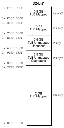
The main R4300i processor has a huge role in deciding where memory is placed and how it is placed through the Control Processor (CP) which acts as a coprocessor. The CP is composed of the Translation Lookaside Buffer (TLB) and a Memory Management Unit (COP0). The Nintendo 64 is a single user system, meaning it normally just runs in one kernel mode. All addresses related to the CPU are NOT physical addresses, they're always virtual addresses. The kernel can be either in 32 or 64-bit addressing mode, but usually for performance reasons it's 32-bit. The manner in which memory addresses are translated or mapped depends on the operating mode of the CPU. The following is a table for virtual address translation in 32-bit kernel addressing mode (mapped meaning mapped through the MMU):
| Address Range | ID | Comments |
|---|---|---|
| 0x80000000 - 0x7FFFFFFF | KUSEG, USEG, SUSEG TLB map (User Mode) | Accessible in all modes |
| 0x80000000 - 0x9FFFFFFF | KSEG0 Direct map (Cached Memory) | Accessible in kernel mode, not mapped |
| 0xA0000000 - 0xBFFFFFFF | KSEG1 Direct map (Non-cached Memory) | Accessible in kernel mode, not mapped |
| 0xC0000000 - 0xDFFFFFFF | KSSEG, SSEG TLB mapping (Supervisor Mode) | Accessible in kernel or supervisor mode |
| 0xE0000000 - 0xFFFFFFFF | KSEG3 TLB mapping (Kernel Mode) | Accessible in kernel mode |
Operating Modes
The only difference between KUSEG, KSSEG, and KSEG3 is the virtual address space. KUSEG is the "user" address space accessible from kernel mode (this is the same address space accessible from user mode). KSSEG is the "supervisor" address space (same address space as accessible in supervisor mode), and KSEG3 is one of the three address spaces accessible only from kernel mode (and the only segment of the three that is mappable via TLB).
- User Mode: In the single-user mode, a virtual address space of 2 GB can be used in the 32-bit mode. (Will explain more.)
- Supervisor Mode: Will explain.
- Kernel Mode: Will explain.
Cached and Non-cached Memory
In the logical memory hierarchy, the caches lie between the CPU and main memory. They are designed to make the speedup of memory accesses transparent to the user. In attempt to create a proper frame of mind around cached and non-cached memory: Even if a game is allocated to the uncached memory of kernel mode KSEG1, data is still present in it's cached counterpart KSEG0. By that I mean, they point to the same physical address; all writes between locations are accessible by each other. You obtain performance gains by using non-cached memory, but only in tight loops (a loop that iterates many times/plays an important role in the games performance). Like not having to flush the CPU cache when running a lot of cycles in a short time. The only time you care about cache is when writing self-modifying code, or when doing silly interleaved access between each address space.
Note, if you're ever feeling froggy or get a wild hair caught up your ass and want to make a really big TLB page, be sure to keep your peripherals away from your cached address space by placing them near the top of your address space.
Exception and Interrupt Processing
Main article: Exceptions and Interrupts
The processor receives exceptions from a number of sources, including translation lookaside buffer (TLB) misses, arithmetic overflows, I/O interrupts, and system calls. When the CPU detects an exception, the normal sequence of instruction execution is suspended and the processor enters Kernel mode. The processor then disables interrupts and forces execution of a software exception process (called an exception handler) located at a fixed address. The handler saves the context of the processor, including the contents of the program counter, the current operating mode (User or Supervisor), and the status of the interrupts (enabled or disabled). This context is saved so it can be restored when the exception processing has been performed.
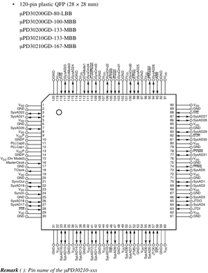
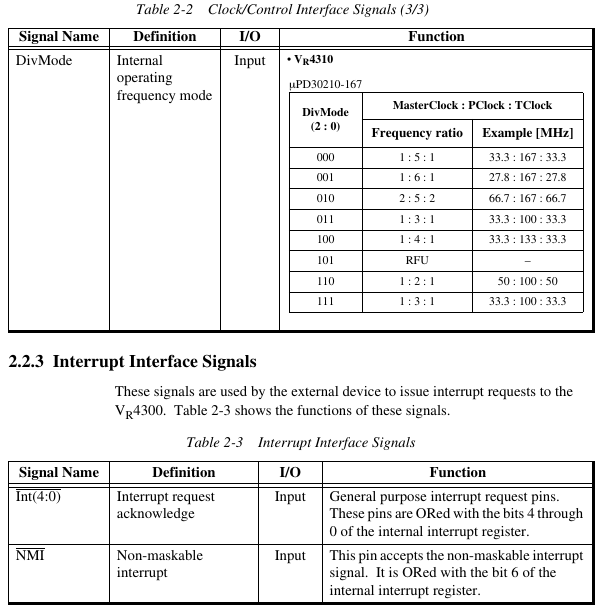
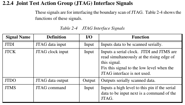
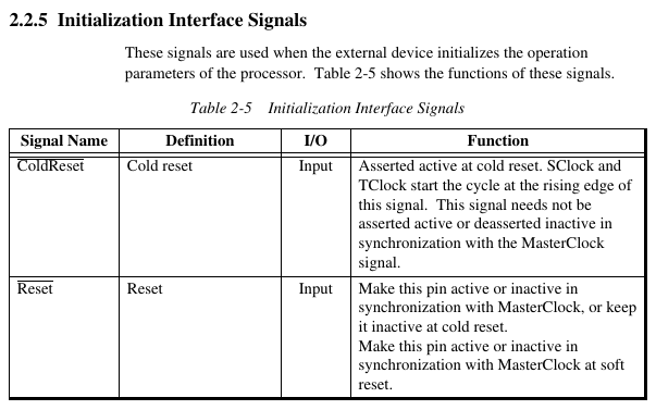
NEC VR4300 Pinout
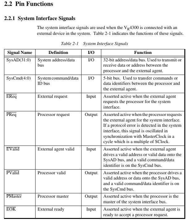
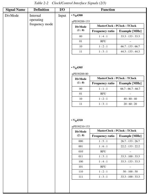
The following is from the VR4300 manual.
| Name | Description |
|---|---|
| ColdReset | Cold Reset |
| DivMode (1:0)* | Divide Mode |
| EOK | External OK |
| EReq | External Request |
| EValid | External Valid |
| Int (4:0) | Interrupt Request |
| JTCK | JTAG Clock Input |
| JTDI | JTAG Data In |
| JTDO | JTAG Data Out |
| JTMS | JTAG Command Signal |
| MasterClock | Master Clock |
| NMI | Non-maskable Interrupt Request |
| PLLCap (1:0) | Phase Locked Loop Capacitance |
| PMaster | Processor Master |
| PReq | Processor Request |
| PValid | Processor Valid |
| Reset | Reset |
| Syncln | Synchronization Clock Input |
| SyncOut | Synchronization Clock Output |
| SysAD (31:0) | System Address/Data Bus |
| SysCmd (4:0) | System Command Data ID Bus |
| TClock | Transmit Clock |
| VDD | Power Supply |
| GND | Ground |
| VDDP | VDD for PLL |
| GNDP | GND for PLL |
* In the mPD30200- ́ ́ ́. DivMode (2:0) in the mPD30210- ́ ́ ́.
